2008 Jeep Grand Cherokee Diesel Fuse Box Diagram
Fuse box diagram (fuse layout), location, and assignment of fuses and relays Jeep Grand Cherokee (WK) (2005, 2006, 2007, 2008, 2009, 2010).

Checking and Replacing Fuses
A fuse is an element for protecting the electrical system. A fuse will trip (i.e. it will blow) in the event of a failure or improper interventions in the electrical system.
If an electrical device is not working, check whether the respective fuse is blown. Look at the silver-colored band inside the fuse. If the band is broken or melted, replace the fuse. Check those fuses first that protect the failed component, but check all the fuses before deciding that a blown fuse is not the cause. Replace any blown fuses with another with the same amperage (same color) and check the component's operation.
Notice
- Before changing a fuse, check the ignition key has been removed and that all the other electric devices have been turned off/disabled.
- Never replace a broken fuse with anything other than a new fuse. Always use a fuse of the same color.
- Never change a fuse with another amperage. This can cause damage to the electrical system and fire.
- If the fuse blows again, have the vehicle inspected at a qualified service center.
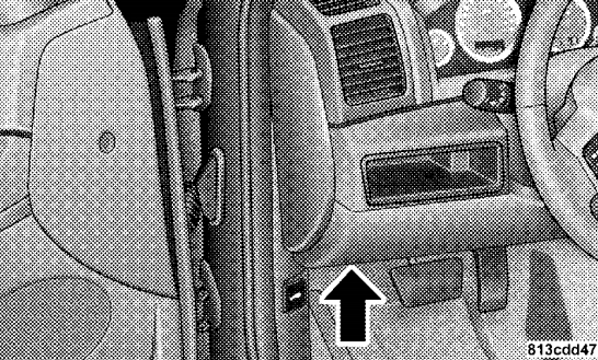
Passenger Compartment Fuse Box
The fuse panel is on the lower instrument panel just to the left of the steering column.
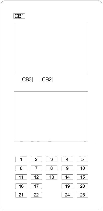
Rear Side
| № | A | Protected Component |
|---|---|---|
| 1 | 30 | Audio Amplifier |
| 2 | 15 | Sunroof Module |
| 3 | 10 | Heated Mirror |
| 4 | 20 | Rear Power Outlet |
| 5 | 10 | Rear HVAC |
| 6 | 10 | 2005-2007: Occupant Classification Module |
| 7 | 20 | Door Lock Relay, Driver Door Unlock Relay, Passenger Door Unlock Relay |
| 8 | 15 | 2005-2007: Steering Column Lock |
| 9 | 20 | Power Outlet (Console) |
| 10 | 10 | Rear Window Defogger Relay, Blower Motor Relay, Upper Switch Bank, Lower Switch Bank, A/C Heater Control, Final Drive Control Module, Park Assist Module, Electronic Overhead Module, Inside Rearview Mirror |
| 11 | - | - |
| 12 | 10 | Courtesy Lamp, Glove Box Lamp, Cargo Lamp, Vanity Lamp, Door Handle Lamp, Mirror Switch, Memory Mirror Module |
| 13 | 10 | 2008-2010: Automatic Windshield Wipers (Rain Sensor) |
| 14 | 20 | Power Outlet (Instrument Panel) |
| 15 | 10 | Tire Pressure Monitoring System, Fuse (Engine Compartment №2): "30" |
| 16 | 10 | Cluster, Steering Control Module, Data Link Connector |
| 17 | 15 | Flip-Up Glass Relay |
| 18 | - | - |
| 19 | 10 | 2005-2007: Occupant Classification Module |
| 20 | 10 | Sentry Key Remote Entry Module (2005-2008), Cluster, Steering Column Control Module (2008-2010), BUX Trailer Tow (2008-2010) |
| 21 | 15 | 2005-2007: Automatic Windshield Wipers (Rain Sensor) |
| 22 | 15 | Rear Wiper Relay |
| 23 | - | - |
| 24 | 10 | Transmission Relay, Air Conditioner Compressor Clutch Relay, Fuel Pump Relay, Stop Lamp Switch (5.7L), Powertrain Control Module, Front Control Module |
| 25 | 10 | Stop Lamp Inhibit Relay, ABS, Transfer Case Selector Switch |
| | ||
| CB1 | 20 | Wiper (On/Off) Relay (Wiper (High/Low) Relay) |
| CB2 | 20 | Power Seat, Heated Seat Module |
| CB3 | 20 | Power Window, Door Lock, Mirror Switch |
| | ||
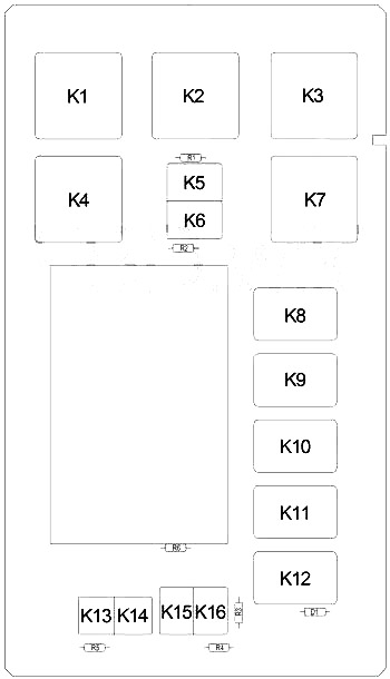
| K1 | - | |
| K2 | Power Outlet | |
| K3 | - | |
| K4 | Rear Window Defogger | |
| K5 | Run/Accessory | |
| K6 | Run | |
| K7 | Run/Accessory Delay | |
| K8 | Stop Lamp Inhibit | |
| K9 | - | |
| K10 | - | |
| K11 | Flip-Up Glas | |
| K12 | Transmission | |
| K13 | Door Lock | |
| K14 | Driver Door Unlock | |
| K15 | Passenger Door Unlock | |
| K16 | Rear Wiper | |
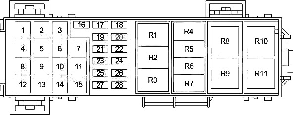
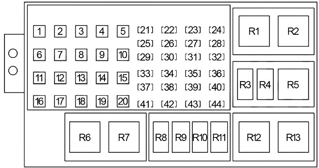
Engine Compartment Fuse Box №1
Power Distribution Center
Diagram (2005-2007)
| № | A | Protected Component |
|---|---|---|
| 1 | 40 | Blower Motor Relay |
| 2 | 30 | Fuse (Passenger Compartment): "4", "9" |
| 3 | 30 | Run Relay, Fuse (Passenger Compartment): "12", "17", "22" |
| 4 | 30 | ABS |
| 5 | 50 | Diesel: Cabin Heater |
| 6 | 50 | Auto Shut Down Relay (Powertrain Control Module, Fuse: "16") |
| 7 | 30 | - |
| 8 | 40 | Run/Accessory Delay Relay, Fuse (Passenger Compartment): "2", "7", "8", "CB2" |
| 9 | - | - |
| 10 | 40 | Starter Relay, Run/Accessory Relay, Fuse (Passenger Compartment): "CB1" |
| 11 | 30 | Power Outlet Relay |
| 12 | 40 | Rear Window Defogger Relay |
| 13 | 40 | Run Relay, Run/Accessory Relay, Rear Wiper Relay, Door Lock Relay, Driver Door Unlock Relay, Passenger Door Unlock Relay, Fuse (Passenger Compartment): "1", "6", "16" |
| 14 | - | - |
| 15 | - | - |
| 16 | 25 | Zener Diode, Front Control Module, Ignition Coils (3.7L, 4.7L, 5.7L), Ignition Capacitor (3.7L, 4.7L) |
| 17 | - | - |
| 18 | 20 | Gasoline: Air Conditioner Compressor Clutch Relay, Transmission Control Relay (4.7L, 5.7L) |
| 19 | 20 | Ignition Switch (Starter Relay, Powertrain Control Module, Fuse (Passenger Compartment): "19", "20", "24", "25") |
| 20 | 20 | Gasoline: Powertrain Control Module |
| 21 | 30 | ABS |
| 22 | - | - |
| 23 | 20 | Final Drive Control Module |
| 24 | 20 | Gasoline: Fuel Pump Relay, Hydraulic Cooling Fan (5.7L) |
| 20 | Diesel: Hydraulic Cooling Fan, Fuel Pump Relay | |
| 25 | 20 | Final Drive Control Module |
| 26 | 15 | Diesel: Powertrain Control Module |
| 27 | 15 | Stop Lamp Switch |
| 28 | 25 | Fuel Injectors, Powertrain Control Module |
| | ||
| R1 | - | |
| R2 | - | |
| R3 | Diesel: PTC (№1) | |
| R4 | Transmission Control | |
| R5 | Starter | |
| R6 | Air Conditioner Compressor Clutch | |
| R7 | Fuel Pump | |
| R8 | Diesel: PTC (№3) | |
| R9 | Diesel: PTC (№2) | |
| R10 | Blower Motor | |
| R11 | Auto Shut Down | |
Diagram (2008-2010)
| № | A | Protected Component |
|---|---|---|
| 1 | 50 | Diesel: PTC (№1) |
| 2 | 40 | HID Headlamps |
| 3 | 50 | Diesel: PTC (№2) |
| 4 | 30 | Power Outlets |
| 5 | 50 | Diesel: PTC (№3) |
| 6 | 30 | Cigarette Lighter, Trailer Tow Battery |
| 7 | 40 | - |
| 8 | 40 | Starter, JB Power |
| 9 | 20 | Front Power Windows |
| 10 | - | - |
| 11 | 40 | Blower Motor Relay |
| 12 | 30 | Rear Wiper, Ign R/O |
| 13 | 40 | Rear Window Defroster, Heated Mirror |
| 14 | 30 | Rear Blower Motor |
| 15 | - | - |
| 16 | 50 | Auto Shut Down Relay |
| 17 | 30 | ABS Pump |
| 18 | 40 | Accessory Delay, Power Seats |
| 19 | 40 | JB Power |
| 20 | 30 | Front Wiper Motor |
| 21 | 20 | Fuel Pump |
| 22 | 20 | Transmission Control Module (TCM), Air Conditioner Compressor Clutch |
| 23 | 25 | Power Inverter |
| 24 | 20 | Rear Heated Seats |
| 25 | 20 | Final Drive Control Module (FDCM) |
| 26 | 15 | Stop-Lamps |
| 27 | 20 | Headlamp Washer |
| 28 | 30 | ABS Valves |
| 29 | 20 | Gasoline: Powertrain Control Module (PCM) |
| 30 | - | - |
| 31 | - | - |
| 32 | 15 | Diesel: Powertrain Control Module |
| 33 | 20 | E-Diff - Final Drive Control Module (FDCM) |
| 34 | - | - |
| 35 | 20 | Trailer Tow Module (BUX Only) |
| 36 | - | - |
| 37 | 20 | Ignition Switch |
| 38 | 20 | Left Headlamp (HID) |
| 39 | 20 | Right Headlamp (HID) |
| 40 | 25 | Next Generation Controller (NGC), Injectors |
| 41 | 20 | SRT: Subwoofer |
| 42 | - | - |
| 43 | 25 | Coils, Actuators |
| 44 | - | - |
| | ||
| R1 | - | |
| R2 | Diesel: PTC (№3) | |
| R3 | Transmission Control | |
| R4 | Headlamp Washer | |
| R5 | HID Headlamps | |
| R6 | Diesel: PTC (№1) | |
| R7 | Diesel: PTC (№2) | |
| R8 | Ignition (Run/Start) | |
| R9 | Air Conditioner Compressor Clutch | |
| R10 | Fuel Pump | |
| R11 | Starter | |
| R12 | Blower Motor | |
| R13 | Auto Shut Down | |
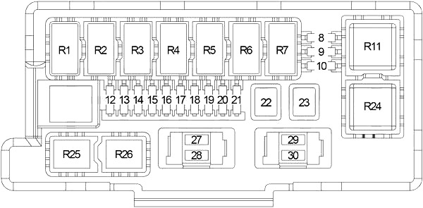
Engine Compartment Fuse Box №2
Integrated Power Module
| № | A | Protected Component |
|---|---|---|
| 8 | 10 | Left Headlamp, Left Tail Lamp, License Lamp |
| 9 | 10 | Trailer Tow Connector |
| 10 | 10 | Right Headlamp, Right Tail Lamp, Cluster, Upper Switch Bank |
| 12 | 20 | Front Control Module |
| 13 | 20 | Front Control Module |
| 14 | 20 | Adjustable Pedals Relay |
| 15 | 20 | Front Fog Lamp Relay |
| 16 | 20 | Horn Relay |
| 17 | 20 | Rear Fog Lamp |
| 18 | 20 | Front Control Module |
| 19 | 20 | Trailer Tow (Left Turn) Relay |
| 20 | 20 | Front Control Module |
| 21 | 20 | Trailer Tow (Right Turn) Relay |
| 22 | 30 | Final Drive Control Module |
| 23 | 50 | Radiator Fan (High Speed) Relay, Radiator Fan (Low Speed) Relay |
| 27 | 15 | Front Control Module, Sentry Key Remote Entry Module, Electronic Overhead Console, Satellite Receiver |
| 28 | 20 | Radio |
| 29 | 10 | Occupant Restraint Controller Module |
| 30 | 10 | Occupant Restraint Controller Module |
| | ||
| R1 | Wiper (On/Off) | |
| R2 | Wiper (High/Low) | |
| R3 | Horn | |
| R4 | Rear Fog Lamp | |
| R5 | Trailer Tow (Left Turn) | |
| R6 | Trailer Tow (Right Turn) | |
| R7 | Park Lamp | |
| R11 | Radiator Fan (High Speed) | |
| R24 | Radiator Fan (Low Speed) | |
| R25 | Front Fog Lamp | |
| R26 | Adjustable Pedals | |
This website uses cookies to improve your experience. We'll assume you're ok with this, but you can opt-out if you wish. Cookie settingsACCEPT
Posted by: travismontalgoe0198709.blogspot.com
Source: https://fusecheck.com/jeep/jeep-grand-cherokee-2005-2010-fuse-diagram

Post a Comment for "2008 Jeep Grand Cherokee Diesel Fuse Box Diagram"